Category
New installation of pipes, cables and ducts for gravity and pressure pipe networks.
Application
Suitable for the installation of gas pipes, water pipes, cable ducting, sewer pipes, culverts etc. in a diameter range from 150 mm to approximately 3,000 mm (above this the bore tends to be described as a Tunnel).
The length of bore that can be installed depends on the ground type, the route (if curves are included), the diameter (larger diameters can be bored further), the selection of the machine used for the boring operation and its thrust capacity. The pipe type can also have a significant bearing on drive length.
Microtunnelling can be achieved in a broad range of ground condition from soft, alluvial soils to hard rock. There are variants of machine type, face support and spoil management to deal with unstable soils and high groundwater heads. Limitations are: the thrust capacity of the jacking frame which may limit effective bore length; the compressive strength of the pipe; and the abrasiveness and friction coefficient of the soil through which the bore is undertaken.
The two former are dealt with through effective design and the latter can be managed with lubrication of the external pipe surface during installation.
Benefits
Microtunnelling has the advantages that:
- It minimises the need to excavate long trenches especially in urban environments
- The impact on landscapes and cityscapes is minimal
- Operations are less weather-dependant than open cut trench construction
- Faster operation than open cut construction with less disruption to the surroundings
- Significantly reduced need for large volumes of site traffic to remove excavated soil and return with new backfill material as the volume of spoil removed is only that of the pipe itself plus a small overcut
- It minimises disruption to the site locality, residents and businesses and tends to be operational for a shorter amount of time overall
- Carbon emissions from both installation and site traffic are considerably lower than open cut construction
- It is more environmentally friendly


Technology Description
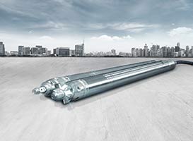
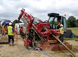
Microtunnelling is a non-disruptive trenchless pipeline installation technique that utilises microtunnel boring machines (MTBMs), usually remote controlled from the surface, to install pipes underground.
The first microtunnelling projects took place in the late 1970s. The MTBM is guided by a steering system which allows the operator to follow the desired route by using steering pistons located just behind the cutterhead. The guidance system may be line of sight laser or more complicated technology specially designed to allow curved bores both in the horizontal and vertical planes. Depending on the type of installation required, potential users of microtunnelling should consult with specialist tunnel navigation system manufacturers or the MTBM manufacturer for the most appropriate system before commencing the project.
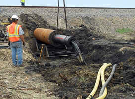
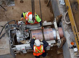
The MTBM is advanced through the ground using specially manufactured jacking pipes which are placed in a jacking frame in a launch shaft at one end of the pipeline route. Pistons in the jacking frame push the pipe and MTBM forward at a controlled rate to ensure effective and safe progress of the MTBM as it cuts the soil.
As each pipe advances the MTBM through the ground one pipe length at a time, the pistons of the jacking frame are withdrawn to allow the next pipe section to be added to the pipe string. This process continues until the MTBM reaches the reception shaft at the far end of the route.
Microtunnelling Options:
There are essentially four main types of microtunnelling technology including:
- Pilot Tube Microtunnelling
- Auger Microtunnelling
- Slurry Microtunnelling
- Earth Pressure Balance Microtunnelling
The latter three systems are full face boring techniques as all the spoil excavation takes place at the same time unlike the multi-phase Pilot Tube technique.
Which method is used depends on the soil and groundwater conditions at the site. It also depends to some extent on the diameter of the bore.
Pilot Tube Microtunnelling (see also Guided Auger Boring)
This is a multi-stage operation that begins with a guided/steerable small diameter pilot tube being installed to create a pilot bore that follows accurately the desired pipeline route. Once this has been completed successfully the pilot tube is used to guide a steel casing of the finished bore diameter along the route. Inside this casing is an auger which excavates the ground around the pilot tube to the desired bore diameter for the pipeline being installed. The spoil is collected using the rotating auger and returned to the launch shaft for collection and disposal. The auger may also be installed in the pilot tube if this is of sufficient diameter with the spoil being transported to the reception shaft for removal.
If required there are independently powered cutting systems that can be placed in front of the final pipe string which assist in excavating the ground the final required diameter. This would normally be used in ground considered too hard for the standard pilot bore machine to handle.
Once the bore has been enlarged to the correct size the final pipes are jacked through the route expelling the steel casings into the reception shaft for use on a later project. When the final casing has been removed and the final pipe section jacked into place the installation is complete and the Pilot Tube Microtunnelling system may be removed from the shaft.
The pilot tube systems are becoming more prevalent in the market as they are smaller and easier to set up. Pilot tube microtunnelling is mainly used at smaller diameters, up to DN600. The pilot tube system is most commonly used for shorter drives which fit well with sewer networks where distances between manholes are relatively short.


Auger Microtunnelling
This method utilises an MTBM that is jacked directly through the ground using the sectional lengths of the final pipeline material.
The spoil from the cutterhead is collected using an auger flight located inside the jacking pipe string or in a steel casing placed inside it. The spoil is returned to the launch shaft for collection and removal.
The pipe string advances the cutterhead one pipe length at a time with new pipe being added when the limit of the jacking frame stroke is reached. Guidance is generally achieved using a line of sight laser system. Once the cutterhead arrives at the reception shaft the MTBM is removed as is any equipment in the pipe string and the installation is complete.
The open face of the cutterhead means that it is limited to ground conditions that are relatively free of ground water. In these conditions it is a fast, effective and economical method of accurate pipe installation.
Slurry Microtunnelling
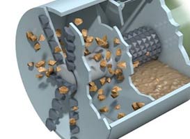
The overall method of pushing the MTBM and pipe string from the launch shaft is as for Auger Microtunnelling but in this instance the cutterhead is not open to the surrounding soils; it is a closed-face method.
The cutterhead is sealed off from the main bore by a bulkhead and the spoil from the excavation is extracted using a slurry which may be simply water or a bentonite- or polymer-based drilling fluid/mud. As the MTBM is advanced through the ground the slurry is pumped through the cutterhead and circulated to a settling tank on surface where the spoil is separated from the slurry and the slurry is reconditioned as necessary to provide the correct consistency and returned to the slurry circulation system for reuse at the face.
The slurry system has the advantage that, given the correct consistency the slurry will act as a face support when maintained under pressure from the pumping system where ground is less competent in nature.
It also removes spoil from the face at a controllable rate which again helps face support in less competent ground. It also prevents ground water ingress into the bore which prevents loss of ground at the face and therefore precludes any loss of ground around and above the bore path.
Management of the slurry properties to remove the correct amount of spoil, provide the correct face support and minimise ground water ingress is a vital part of the success of any slurry microtunnelling project to such an extent that where ground conditions are known to be very wet or where ground variation is expected, the slurry management may be undertaken by a specialist subcontractor with expertise in the field.

Earth Pressure Balance (EPB) Microtunnelling
This again works in the same way as Auger and Slurry Microtunnelling in terms of how the MTBM and pipe string are advanced through the ground. It is a closed-face system. However instead of using a slurry circulation system the excavated spoil is retained under pressure at the face to provide the necessary face support.
This is particularly applicable to unstable ground conditions. A screw system extracts the spoil from within the face compartment only removing the spoil volume necessary to achieve advance while the remainder of the spoil remains under pressure in the cutterhead chamber. The extracted spoil is passed into either a Sludge Pump system or is loaded into an open conveyor or truck system that removes the spoil to the launch shaft for disposal.
Common Factors
Particularly with the full- or closed-face techniques, the advance of the pipe string through the ground may be affected by the settling in of the surrounding ground back onto the outside of the pipes. This is especially the case where the route of the bore contains curves in the horizontal or vertical planes. Whilst the curves may not be tight there will be an increase in friction as the pipe pass through the curvature. This also needs to be managed carefully. These effects will result in an increase in the jacking force necessary to overcome the increasing friction as the bore progresses.
The design and thrust capacity of the jacking frame must be sufficient to overcome this friction.
This effect can be ameliorated by using a lubrication system to apply a lubrication fluid such as a bentonite to the outside surface of the jacking pipes.
To accommodate this, the pipes are manufactured with lubrication ports placed through the pipes to allow the lubricant to reach the annulus between pipe and ground. Lubrication is a common procedure and is almost standard in larger microtunnelling works.
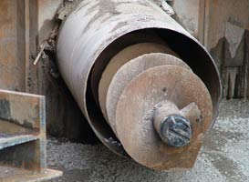
Jacking Pipes
The most common jacking pipe materials are clay, concrete and GRP although other pipe materials have been used on occasions. Jacking pipes are in discrete lengths to enable installation from jacking shafts.
Therefore there are frequent joints in the pipes as new sections are added as the drive advances. It is important that these joints are designed to provide a smooth and linear outside diameter of the bore, so conventional bell and socket joints cannot be used. The joint structure and seal and the compression seals in the joints must be correctly designed to minimise the potential for failure either during the installation process or subsequently once the pipe is in operation.
Pipe manufacturers should be consulted with full details of the expected bore route, ground conditions and machine type to be used to ensure that the correct pipe with the appropriate jacking characteristics (dimensional accuracy, axial load capacity, joint design, etc.) is used on any particular project.
On longer drives at man-entry diameters there is the option to install intermediate jacking stations at intervals along the pipe string. This allows shorter lengths of the pipe string to be advanced at any one time reducing the jacking forces necessary to move the pipe string forward thereby reducing the necessary load capacity of the jacking pipes being used to create the installation as well as reducing the required capacity of the jacking system itself.
Other Microtunnelling Options
There have been variations in microtunnelling over that past 40 years, with new methodologies still being developed. These have included a system where a set of steel cylinders are jacked into place behind the MTBM instead of the final product pipe. Once the bore has been completed the steel cylinders are pushed out of the bore by the final product pipe as it is jacked into place from the launch shaft.
This adds a step so is slower and more costly than direct installation but it does eliminate the potential for jacking pipe failure and the problems this may cause if a pipe fails in mid excavation in the middle of the pipe string. It also reduces the cost of the pipe since it does not need to be designed to resist the full axial load of jacking.
A more recent development is a system that is designed to install very long steel casing pipe directly into the ground. The system uses the standard slurry MTBM for the excavation/boring activity but this is advanced through the ground using a welded steel pipe that is jacked forward using a specially designed thrust unit at the surface that grips it externally so does not require the usual intermittent stoppages as when shorter lengths of segmental pipe are uses as in standard microtunnelling.
The operation can therefore be continuous over a long distance which also eliminates the potential for ground settlement around the pipe which can cause restart problems where long lengths of pipe sit in the ground stationary during pipe changes.

Others in this Category: