Category
New installation of pipes, cables, ducts mainly for pressure networks. Gravity networks may be possible also.
Application
Applications in gas, water, cable duct, rising sewer mains as well as gravity pipelines. Lengths can be variable depending on the installation required and very importantly the ground conditions on site.
Bore lengths range from a few metres to over 1 km with diameters available from as little as 50 mm (2 in) to several hundreds of millimetres. Ground conditions that can be drilled range from soft clays, sands and gravels to mixed grounds and hard rock depending on the equipment used.
Limitations
It is important to understand the ground conditions that will be encountered during the pilot boring and back-reaming operations, the length and diameter of the bores required in order to select the correct drilling rig for the job in hand.
The correct tooling, support equipment etc. also needs to be assessed and provided to ensure that any bore proceeds as smoothly as possible. Each project will require a significant amount of pre-project ground investigation to be carried out, planning and consultation with utility owners and contractors, machine manufacturers and support equipment providers such as drilling fluid removal (possibly specialist subcontractors) may be needed to best design the project parameters for a successful outcome.


Benefits
HDD offers the potential to install new or replacement pipelines, ducts and cabling without the need to excavate large pits and long trenches on the surface making the HDD process environmentally friendly compared to open cut techniques.
The installation, when correctly planned and using the right equipment, can install networks from small to large diameters over a short to long distances safely and with minimal disruption to the surroundings, local businesses and the general public can carry on with their daily business at a lower cost compared with traditional methods when all aspects of the traditional operations are taken into account (including site waste disposal traffic management, possible compensation claims etc.)
Technology Description
HDD is one of the most versatile trenchless methods used for the installation of many product pipelines including service connections, mains pipes, cables, crossings under highways, rail tracks, watercourses, runways, landfill sites etc.
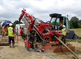
HDD is a multi-phase operation which uses a special design drilling rig which initially bores a pilot hole through the ground along a pre-determined route. Once completed to the satisfaction of the client, this pilot bore is then expanded as necessary using various sizes and types of back-reamers to enlarge the pilot bore to the final diameter into which the product pipe or cable will be installed. This expansion process can be completed in stages depending on how large the product pipe/cable is, normally the final diameter of the bore is between 30-50% larger than the product pipe/cable that is to be installed.
Pre-reaming operations are required for larger bores and can be achieved by adding drill rods to the rear of each successive pre-reaming operation so that once one reaming pass is completed another can take place with a larger back reamer until the final size is achieved.
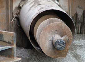
Depending on the ground type the pilot bore drill head and the reamer cutters can be designed for anything from soft clays through sands and gravels to mixed ground conditions (often using a slant/angled drill face) and hard rock (mainly utilising roller cone bits or button bits). Consultation with specialist HDD contractors, machine manufacturers and equipment providers will determine the correct tooling and systems for any bore being carried out.
Once the final diameter is achieved a final back reamer is attached to the drill string to which is attached via a swivel, the product pipe or cable is attached with a Dee Shackle. The final pull-in installs the product pipe/cable into the bore to complete the process.
Generally, HDD is best suited for installing pressure pipes and ducts/conduits where precise grades are not required. However, with the correct skills of the operator and the right locating systems on grade bores are also possible.
Over the years since it first appeared on the market HDD machine technology has seen many and often rapid developments. In recent years numerous additional functions, automated steps, improved mixing units, advanced power transmission, optimised tooling, etc. have been the basis of such developments, in many instances modern machines are now able to achieve bores that previously would have required larger, more powerful HDD machines.
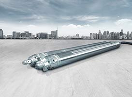
Machine Types
The application of the technology for utility service projects has been taken largely from the oil and gas industry which developed the method to drill to/from offshore installations. For utility applications, various rig types have been developed depending on the application to hand. These include: Mini, Midi, Maxi and Mega rigs
Bore rig (type) | Max. pulling force (kN) | Max. torque (kNm) | Weight (tonnes) |
Mini | 150 | 7 to 13 | <7 |
Midi | >150 to 400 | 15 to 30 | 7 to 25 |
Maxi | >400 to 2,500 | 30 to 100 | 25 to 60 |
Mega | >2,500 to 6000 | >100 | >60 |
Classification of bore rigs in accordance with the DCA Technical Guidelines
An HDD set up comprises of a suitable HDD rig size to be able to undertake the job in hand equipped with sufficient drill rods for the length of the bore required along with a suitable drill bit for the ground conditions and bore expansion back reamers to provide the correct diameter into which the product pipe or cable will be installed.
The selection of drilling rig is totally dependent on the ground conditions and type, the length and diameter of the bore and the product type being installed. Users will have to investigate and consult with experienced operators and equipment suppliers to ensure the correct combination of rig and tooling and back-up equipment is selected for the job in hand – bearing in mind that no matter how similar it is likely that no two will be exactly alike.
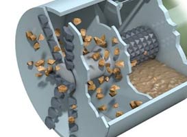
It is usual for the drilling process to be supported using a drilling fluid system which is pumped down the drill rods to the drill head. The drilling fluid may on shorter bores simply comprise a flow of water, often the drilling fluid is a specially formulated drilling mud comprising a mixture of water/bentonite/polymer additives depending on the project circumstances.
This fluid is usually design for three main purposes:
- Flushing the drill cuttings out of the bore during the pilot boring operation and keeping the cuttings in suspension whilst the cuttings are transported out of the bore.
- Lubricating the bore and creating a filter cake for stabilization of the bore walls.
- It is very important that the Sonde/Transmitter is kept cool during the pilot boring operation as overheating the Sonde/Transmitter can be costly to the drilling contractor.
- Cooling of the drill bit during the pilot boring operation.
- Providing ground support for the bore walls to ensure that bore does not collapse behind the drill head as it advances.
This aspect of the drilling operation may be very specialised and might require the employment of a specialist contractor to design the fluid to suit the ground conditions and to maintain the drilling fluid properties to that specification during the drilling operation. This usually requires the use of specially designed drilling fluid mixing systems, holding tanks, the selection of the correct additives to provide the right balance of cutting removal, cooling and bore support and pumps.
If the drilling fluid is to be recycled, as is often the case on most of the larger drilling machines, there is a need for a recycling system this will have shakers and cyclones to separate the solids from the bentonite prior going back into the mixing system before new bentonite being mixed and the process is repeated keeping the drilling/backreaming/hole opening to continue.

Guidance
HDD as the name suggests has a directional control component that makes the system useful to the buried services and utility industries. This directional control is achieved using specially designed drill head location technology. There are two forms of guidance which are used depending on the type of installation being undertaken, the ground conditions, the obstacles that occur along the route of the bore and the local environment (potential interference sources).
Walk-Over Locating System
The sonde emits a radio signal on a known frequency that is detectable on surface using a suitably tuned receiver, usually hand-held by an operative walking over the drill head location.
The receiver is designed to not only locate the strongest sonde signal by the operator passing it over the expected sonde location but can also provide an indication of sonde depth, direction of the sonde/transmitter housing heading, temperature of the Sonde/transmitter, signal strength giving the operator accurate readings.
The sonde housing rotates with the drill string and emits a signal that enables the drilling rig operator to understand where the drill head is beneath the ground its depth and importantly its orientation both vertically and horizontally.
This position can then be compared with the planned bore route and steering corrections made as necessary. The drill head is normally angled so that when rotating it will follow a straight course. If, however the drill head is kept as a known angle to the direction of the bore it will ‘steer’ the drill head in a known direction thereby bring any deviation back to zero and maintaining the planned course. This is effective in softer ground only where the drill head can be advanced without the need to cut ground.
Where rock boring drill heads are used it is usual to have the drill bit and the steering sub/bent sub separate. This orientates the drill bit in the direction required so that it can continue to rotate and drill whilst maintaining a steering action.
Where obstacles may be too dangerous to allow personnel access (busy roads, motorways, rivers etc.) Some guidance systems allow the receiver to be place in a known location ahead of the drill head where it can still receive information that is sufficient to guide the drill operator provided the distance between sonde and receiver is not too great. Adjustments can then be made to ensure the correct course once the drill head can be Walked Over once the obstacle has been negotiated.
Where there may be interference caused by say overhead power lines this system may be affected and provide incorrect readings on the receiver – users should be aware of this potential.
In circumstances where interference is too great to adjust for or where depth is greater than the receiver can be successfully utilised or where obstacles are so large as to negate the use of any type of Walk-Over system, the other option is the Wire-Line system where there is a physical connection between surface and the drill head.
Wire-Line systems
Wire-Line systems do not have a surface receiver as such and rely on instrumentation located behind the drill head that is connected to surface by a physical hard-wire. The instrumentation generally comprises some form of inclinometer with a gyro compass or similar to provide orientation data for the drill head.
The operator compares this data with the expected data for the advance achieved to the point of measurement and steers the drill head accordingly to adjust any misalignment.
This may be a highly skilled technology requiring expert analysis and steering adjustments on very long bores. It is often the case that a specialist subcontractor may be used for this aspect of such a bore.
Ground Preparation
Whilst in most cases HDD can be started directly into the ground if geology is such that there is a possibility of damage or failure of the bore it may be necessary to prepare the launch site of the HDD rig prior to commencing drilling. For example, although not exclusively, if the surface geology is a gravel layer over laying the soils through which the bore will ultimately pass, it may be necessary to inset a guide tube through the gravel from surface to the main soil horizon to prevent loss of drilling fluids and to stabilise the bore wall. The diameter of such a tube may be such that not only will the pilot bore be effectively completed but also the final diameter of the larger reamer will pass through the tube unhindered. This is an option, if ground conditions dictate, that may be necessary on both the start and reception ends of a bore. A full geological investigation should be completed to avoid complications on site prior to starting work.
Drilling Options
There are generally two options for initiating an HDD bore: Pit launched and Surface Launched.
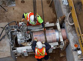
Pit Launched HDD
This option is not as widely used for initiating an HDD bore as Surface launched but does have its place in the sector due to the relatively smaller footprint for the site set-up. As the name suggests this option utilises the HDD machine from within a start pit or shaft.
Where site access is limited but where there is sufficient room to excavate a small shaft a small dimension drill rig may be positioned in the base of the excavation or shaft, also by using this method the bore can be started on a level plane orientated more or less in the direction the bore will follow. In most cases this option is used for shorter smaller diameter bores beneath roads and rail tracks and smaller waterways.
Given the limited space within the shaft the drill rods used tend to be shorter, but the process is basically the same as any other HDD operation. If space is very limited it may be that operators’ station is on the surface with access to the machine only being necessary for insertion or extraction of drill rods.
Most recently development now also include the option to use HDD from within existing manholes using a specially developed rig which operates almost entirely from surface through the manhole access including feeding and extraction of the drill rods. This means of course that no additional ground excavation is necessary to complete an installation. Guidance in these instances is usually of the Walk-Over variety.
This section may be used a tool tip against the highlighted Surface Launched wording in the sentence above or may be used as a continuation of the paragraph.
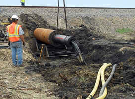
Surface Launched
 For surface launched HDD projects the drill rig is usually larger and longer than those found in pit launch works. The rig is set up along the direction of the bore and the planned exit position with its drill rack angled between 8° to 16°.
Any additional drill rods, reamers, swivels etc. as well as the prepared product pipe/cable are positioned at the reception side of the bore in readiness for use on completion of the pilot bore. When drilling fluids/muds are used, the launch pit is generally deepened to capture the cuttings returning, contaminated spoil laden fluids with a similar pit at the reception side to catch fluids once the pilot bore is completed.
The drill string comprises of a series of drill rods designed to fit the drill rack which advances the drill string and drilling head using a combination of rotation and thrust operations either through a rack and pinion, chain system or a hydraulic ram (although the latter in modern machines is now rarer).
When using the smaller rigs, the need to use a drilling fluid/mud may not usually be necessary again this will depend on the geology/ground conditions particularly for service pipe and cable installation apart perhaps in areas of poor ground conditions. For smaller drilling operations, the returned material can be removed by vacuum technology for disposal.
However, for economical and efficiency reasons, for larger projects it is normal practice to recycle the drilling fluid as described previously.
Larger rigs require much larger operating sites and significantly more back-up equipment and consumables so there may be significant logistical obstacles to overcome and to maintain supplies, remove waste and access machinery etc. so launch site should be chosen with care in consultation with expert operators.
Longer bore will also require significant ground area on the reception side of the bore to allow for pipeline/cable preparation and lay-out prior to installation as well as access for the delivery of product and other equipment required during the back reaming/hole opening operations that may be necessary. The logistics of a larger diameter long HDD installation should not be underestimated.
Others in this Category: