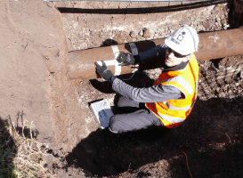
Direct Pipe Wall Condition Inspection
Inspection of pipelines may be necessary to measure pipe condition, for example corrosion, loss of wall thickness, reduction in stiffness or other effects of stresses.
Remote Field Eddy Current (RFT) is a method of non-destructive testing using low-frequency AC to find and measure defects in metallic pipes. An RFT probe consists of an exciter coil (also known as a transmit or send coil) which sends a signal to a detector (or receive coil). The AC current is passed through the exciter coil which creates a magnetic field. The field travels outwards from the exciter coil, through the pipe wall, and along the pipe. The detector is placed inside the pipe two to three pipe diameters away from the exciter and detects the magnetic field that has travelled back from the outside of the pipe wall. In areas of metal loss, the field arrives at the detector with a faster travel time and greater signal strength due to the reduced path through the metal. Measuring the distance of the emitter into the pipe highlights the location along the pipe length of the defect.
Near Field Eddy Current (BEM or NFT) technology uses two coils — a transmitter and a receiver. Typically the receiver coil is close to the transmitter coil, taking advantage of the transmitter’s near-field zone — that is, the zone where the magnetic field from the transmitter coil induces strong eddy currents, axially and radially, in the tube wall. The probes operate within the same frequency range as Remote Field Eddy Current (RFT) probes. NFT is specifically suited to detecting corrosion, erosion, and pitting inside ferrous metal pipes.
 Magnetic Flux Leakage (MFL) – Magnetic flux leakage (also known as TFI or Transverse Field Inspection technology) is a magnetic method of non-destructive testing used to detect corrosion and pitting in metallic pipes. The principle uses a powerful magnet to magnetise the steel in the structure. Using an MFL tool a magnetic detector is placed between the poles of the magnet to detect the leakage field. At areas where there is corrosion or missing metal, the magnetic field ‘leaks’ from the metall. Trained specialists interpret the recording of the leakage field to identify damaged areas and to estimate the depth of metal loss. Typically, an MFL tool consists of two or more bodies, one carrying the magnet and sensors and the other containing the electronics and batteries. The magnet body houses the sensors that are located between powerful rare-earth magnets. The magnets are mounted between the brushes and tool body to create a magnetic circuit along, within and through the pipe wall. As the tool travels along the pipe, the sensors detect interruptions in the magnetic field. Interruptions are typically caused by metal loss which in most cases indicates corrosion, and the dimensions of the potential metal loss are identified. Features other than corrosion will also be highlighted, for example manufacturing defects and mechanical damage such as shovel gouges. The technology indicates length, width and depth of the defect as well as its radial position around the pipeline. The sensors detect the changes in the magnetic field in the three directions (axial, radial, or circumferential) to enable the anomaly to be characterised. The sensors are typically oriented axially which limits data to axial conditions along the length of the pipeline. An MFL tool can take sensor readings based on either the distance the tool travels or on increments of time. The choice depends on many factors such as the length of the run, the speed that the tool intends to travel, and the number of stops or outages that the tool may experience. The second body contains the electronics tool and the batteries, and in some cases an IMU (Inertial Measurement Unit) to tie location information to GPS coordinates. On the very rear of the tool are odometer wheels that travel along the inside of the pipeline to measure the distance and speed of the tool.
 Ultrasonic methods (UT) – Ultrasonic non-destructive testing is a method of characterising the thickness or internal structure of a structure under test through the use of high frequency sound waves. The frequencies used for ultrasonic testing are many times higher than the limit of human hearing, most commonly in the range from 500 KHz to 20 MHz. Ultrasonic testing is widely used on metals, plastics, composites, and ceramics. High frequency sound waves are very directional, and they will travel through a medium (like steel or plastic) until they encounter a boundary with another medium (like air), at which point they reflect back to their source. By analysing these reflections it is possible to measure the thickness of a structure, or find evidence of cracks or other hidden internal flaws. In ultrasonic testing, an ultrasound transducer connected to a diagnostic machine is passed over the object being inspected. The transducer is typically separated from the test object by a couplant which may be oil or water, for example. There are two methods of receiving the ultrasound waveform, reflection and attenuation. In reflection (or pulse-echo) mode, the transducer performs both the sending and the receiving of the pulsed waves as the sound is reflected back to the device. Reflected ultrasound comes from an interface such as the back wall of the object or from an imperfection within the object, for example a pipe crack. The diagnostic machine displays these results in the form of a signal with an amplitude representing the intensity of the reflection and the distance, based on the time of flight of the reflected signal. In attenuation (or through-transmission) mode, a transmitter sends ultrasound through one surface, and a separate receiver detects the amount that has reached it on another surface after traveling through the medium (pipe wall). Imperfections or other conditions in the space between the transmitter and receiver reduce the amount of sound transmitted, thus revealing their presence. Using the couplant increases the efficiency of the process by reducing the losses in the ultrasonic wave energy due to separation between the surfaces.
Coating Defect Surveys and Pipe Current Mapping – There are two main techniques for the undertaking of a Coating Defect Survey: Direct Current Voltage Gradient (DCVG) survey; and Pearson Coating Survey.
DCVG is an accurate and economic means of locating coating defects. When a DC current is applied to a pipeline in a similar manner to cathodic protection, ground voltage gradients are created due to passage of current through resistive soil. Well coated pipelines have a high resistance to earth. Where there are defects, measurable voltage gradients can be detected at ground level and the larger the defect, the greater the current flow. By applying a DC current to a pipeline at a regular pulsed frequency using interrupters enables coating defects to be distinguished. Defects found by a DCVG survey can be sized and mapped by GPS coordinates.
The Pearson Coating Survey is a survey technique to detect external coating defects, which employs an AC signal impressed onto a pipeline and compares the potential gradient between two mobile earth contacts. At coating defects increases in voltage gradient occur which are noted and recorded as the survey progresses.
Pipe to soil potential – stray current mapping – pipe-to-soil potential is the voltage potential generated between a buried pipe and its surrounding soil as a result of electrolytic action and a cause of electrolytic corrosion of the pipe. Detection of this phenomenon is achieved using stray current mapping which is a safe and cost-effective way of mapping the magnitude and direction of stray current interference on a pipeline. When pipe coatings are damaged a destructive chemical reaction occurs at the point of the defect, this causes current to flow from the pipe to the ground. This current and any other in the pipeline from other sources is known as stray current. These can significantly contribute to the corrosion process. Stray current mapping devices allow survey that can completely map and accurately pinpoint where current discharge is taking place from above ground without connection to the pipeline. Various systems are available and can be single survey or term monitoring systems which are used over several hours to determine the stray current activity.
MULTI-SENSOR ROBOTS
Multi-sensor robots for use in pipelines essentially utilise combinations of some of the technologies listed on a single carriage or crawler. This can include CCTV, sonar and laser profilers in sewers. They can also utilise in-pipe GPR (Ground Penetrating Radar), also known as Pipe Penetrating Radar (PPR), and LIDAR (Light Detection And Ranging).
Sonar Surveys
Category
Inspection and Detection for pipes and ducts both Gravity and Pressure.
Laser profiling projects a laser line onto the internal circumference of the pipe being inspected. This is viewed and the image captured by a CCTV camera. The resulting image can be measured to provide an accurate profile of the inside of the pipe. This shows any ovality, encrustation, loss of wall material due to corrosion, etc.
Application
The laser profiler is usually used in conjunction with a CCTV inspection system that is crawler-mounted. These systems may be used in sewers, water mains, gas mains, culverts, rising mains etc. Normal practice is for the pipe to be empty, as for CCTV, although some systems will operate in gravity pipes that are partly full but Will provide data only for the area above the surface of the liquid.
Systems are available for use with crawler-mounted CCTV systems in the full range of diameters in which they operate, above and can be used over almost any length, this being dependant on the length and capacity of the umbilical cable
Limitations are that the pipeline should be as clean as possible to ensure the best view of the inner surface with obstructions removed when encountered.
Benefits
Laser profiling enables engineers to view and measure the changes in diameter of the inner surface of a pipeline without the need for man-entry operations It can highlight defects and provide a permanent record of the state of the asset at the time of the survey, as a baseline against which to measure any future deterioration in subsequent surveys, thus adding to the data recorded by using CCTV alone.
The system can be used to determine the extent to which a pipeline has deformed and therefore the type of renovation or replacement technology that might be employed to provide a working solution to any problems occurring in the pipeline. Data and images from currently available systems can often be accessed via the internet or Wi-Fi from almost any location enabling survey data to be viewed almost immediately after a survey is completed. This enables immediate responses to be made if any pipeline shows such serious defects that such a response is necessary.
Technology Description
Since its introduction in the early 1970’s, Closed Circuit Television (CCTV) technology has made major advances in its technical capabilities. The addition of a Laser profiling system enables variations in the pipe profile to be determined.
Crawler-mounted CCTV camera systems are usually employed with Laser Profilers as the CCTV image of the projected laser line is what provides the basis on which to measure deformations recorded by the Laser system. During the course of a CCTV survey the laser projects a circular ring onto the inside of the pipeline wall. If the pipe is still circular (or any non-standard shape) the ring profile remains constant in the CCTV image. If the pipe shape changes the shape of the laser ring changes in accordance with the deformation encountered. Thus the change in ring shape indicates the change in the inner profile of the pipeline.
This knowledge is required if a renovation technique is to be employed, particularly where the renovation product is solid state and inflexible to provide the minimum dimensions of the pipe into which the renovation product must fit. For flexible pipes, such as GRP, PE and PVC, it also provides indication of potential incipient structural failure.
Specially designed software facilitates this recording (including images, defect assessment, distance along the survey and notation process) as well as offering immediate access to survey results to the client software.
Armed with this information the design engineer may then design the appropriate renovation method.
This add-on may also be used in conjunction with other additional survey technologies such as Sonar surveying.
Laser Profiling
Category
Inspection and Detection for pipes and ducts both Gravity and Pressure.
Laser profiling projects a laser line onto the internal circumference of the pipe being inspected. This is viewed and the image captured by a CCTV camera. The resulting image can be measured to provide an accurate profile of the inside of the pipe. This shows any ovality, encrustation, loss of wall material due to corrosion, etc.
Application
The laser profiler is usually used in conjunction with a CCTV inspection system that is crawler-mounted. These systems may be used in sewers, water mains, gas mains, culverts, rising mains etc. Normal practice is for the pipe to be empty, as for CCTV, although some systems will operate in gravity pipes that are partly full but Will provide data only for the area above the surface of the liquid.
Systems are available for use with crawler-mounted CCTV systems in the full range of diameters in which they operate, above and can be used over almost any length, this being dependant on the length and capacity of the umbilical cable
Limitations are that the pipeline should be as clean as possible to ensure the best view of the inner surface with obstructions removed when encountered.
Benefits
Laser profiling enables engineers to view and measure the changes in diameter of the inner surface of a pipeline without the need for man-entry operations It can highlight defects and provide a permanent record of the state of the asset at the time of the survey, as a baseline against which to measure any future deterioration in subsequent surveys, thus adding to the data recorded by using CCTV alone.
The system can be used to determine the extent to which a pipeline has deformed and therefore the type of renovation or replacement technology that might be employed to provide a working solution to any problems occurring in the pipeline. Data and images from currently available systems can often be accessed via the internet or Wi-Fi from almost any location enabling survey data to be viewed almost immediately after a survey is completed. This enables immediate responses to be made if any pipeline shows such serious defects that such a response is necessary.
Technology Description
Since its introduction in the early 1970’s, Closed Circuit Television (CCTV) technology has made major advances in its technical capabilities. The addition of a Laser profiling system enables variations in the pipe profile to be determined.
Crawler-mounted CCTV camera systems are usually employed with Laser Profilers as the CCTV image of the projected laser line is what provides the basis on which to measure deformations recorded by the Laser system. During the course of a CCTV survey the laser projects a circular ring onto the inside of the pipeline wall. If the pipe is still circular (or any non-standard shape) the ring profile remains constant in the CCTV image. If the pipe shape changes the shape of the laser ring changes in accordance with the deformation encountered. Thus the change in ring shape indicates the change in the inner profile of the pipeline.
This knowledge is required if a renovation technique is to be employed, particularly where the renovation product is solid state and inflexible to provide the minimum dimensions of the pipe into which the renovation product must fit. For flexible pipes, such as GRP, PE and PVC, it also provides indication of potential incipient structural failure.
Specially designed software facilitates this recording (including images, defect assessment, distance along the survey and notation process) as well as offering immediate access to survey results to the client software.
Armed with this information the design engineer may then design the appropriate renovation method.
This add-on may also be used in conjunction with other additional survey technologies such as Sonar surveying.
Others in this Category: